Target Chamber Ports
The target chamber has an inner radius of 5 m. Beam and diagnostic ports cover the full surface. These are distributed for laser irradiation uniformity for both indirect- and direct-drive targets, and for convenient diagnostic access. The port locations are specified in spherical coordinates, θ-φ. The coordinates for the top of the chamber are 0-0. The elevation angle, θ, increases to 180° at the bottom of the chamber. The azimuthal angle, φ, goes from 0 to 360° counterclockwise around the chamber.
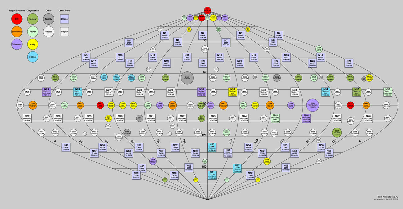
There are 72 ports designated as beam ports (see Figure 5-3). These are located on cones with angles 23.5°, 30°, 44.5°, 50°, and 72.5° from both the top and bottom poles of the target chamber. The 4 cones from 23.5° to 50° are for the indirect drive NIF beam configuration, and the ports at 72.5° from the poles are available for a future symmetric direct drive NIF configuration. A complete listing of the beam ports is provided in Table 4-1.
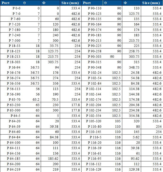
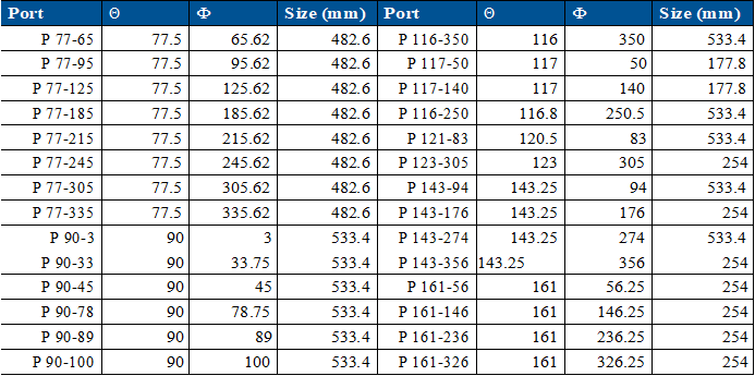
There are diagnostic ports from 18 cm to 53 cm in diameter distributed around the target chamber. These ports are shown on Figure 5-3. Most of these ports are located around the waist of the target chamber and between the upper and lower cones of beams. There are some ports between the different beam cones (37° from the poles) and at the top and near the bottom of the chamber. A listing of the diagnostic port locations is provided in Table 5-1. There are also access ports and ports designated for the alignment systems, including the target positioner (TARPOS). These are described in Section 5.4.
Figure 5-3. View of the NIF target chamber, showing the location of quads and major diagnostics. Diagnostic placement may vary depending on the experimental campaign.
Table 5-1. Diagnostic port sizes and locations. NOTE: The space available behind any one diagnostic port depends on the individual port due to building and utility interferences.


