Laser Configuration
The NIF 192-beam neodymium glass laser is capable of delivering up to 1.8 MJ of total energy and up to 500 TW of peak power at the third harmonic (351 nm, commonly referred to as “3ω”) of the fundamental 1053 nm Nd:YLF wavelength (“1ω”). Since its completion in 2009, the delivered energy and peak power have steadily increased to the peak values mentioned above.
Figure 4-1 identifies the major elements of NIF’s 192-beam architecture. Figure 4-2 shows the schematic of the 192 laser beamline layout. The 1ω section of the laser is arrayed in two laser bays (Laser Bay 1 and Laser Bay 2) in close-packed horizontal configurations to save space and to reduce the cost of both the laser components and the building that houses them. The 96 beams in each laser bay are further grouped in 12 bundles (2 clusters of 6 bundles each), each bundle consisting of 8 beams. Each bundle consists of an array of ash-lamp-pumped Nd:glass amplifier slabs, where the injected ~1 J of 1ω energy is amplified to over 20 kJ per beam.
In the switchyards, each individual bundle is divided into two quads, one each for the upper and lower hemispheres of the chamber. Laser beams enter the chamber at the quad level; that is, the target chamber contains 48 individual laser beam ports (24 in the upper hemisphere, 24 in the lower) with 4 beams passing through each. The quad is the basic independent unit for experiments.
The quads are named with the cluster and bundle number and a suffix that indicates whether the quad is the top (T) or bottom (B) quad in the bundle, such as Q13T or Q45B. Each quad is mapped to a single port on the target chamber. All top quads enter through ports on the top half of the chamber, and all bottom quads enter through ports on the bottom half of the chamber.
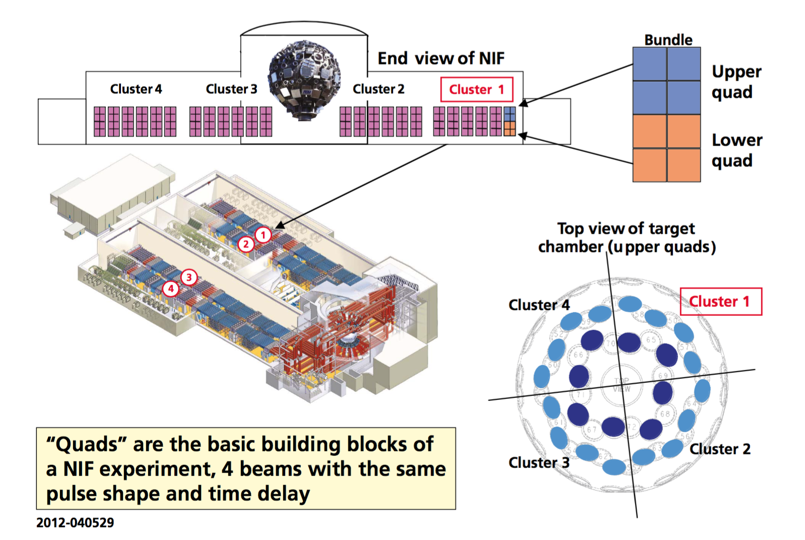
Figure 4-2. NIF is organized into clusters, bundles, and quads of beams.
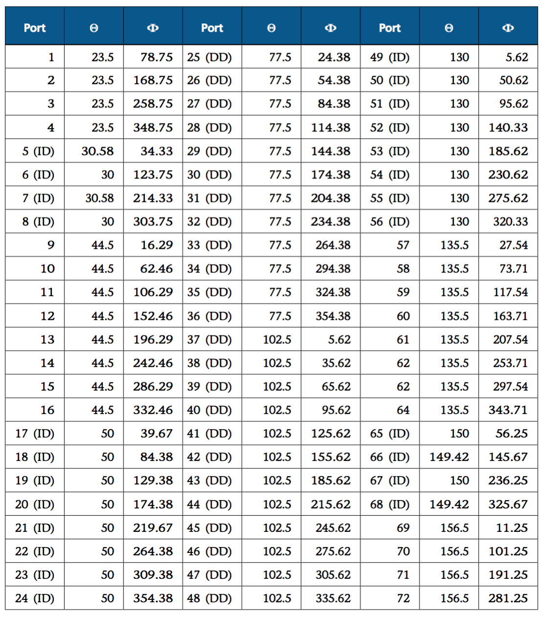
The NIF target chamber is arranged with a vertical z-axis. The quads enter the target chamber through ports that are located on four cones at 23.5°, 30°, 44.5°, and 50° polar angles. The NIF beams are oriented to support indirect-drive hohlraum experiments with the hohlraum mounted vertically (Figure 4-3). Additional ports at 77.5° polar angle are designated for future use in a direct-drive configuration for NIF. A full listing of the beam port angles and cross-reference to the quad numbering is provided in Table 4-1.
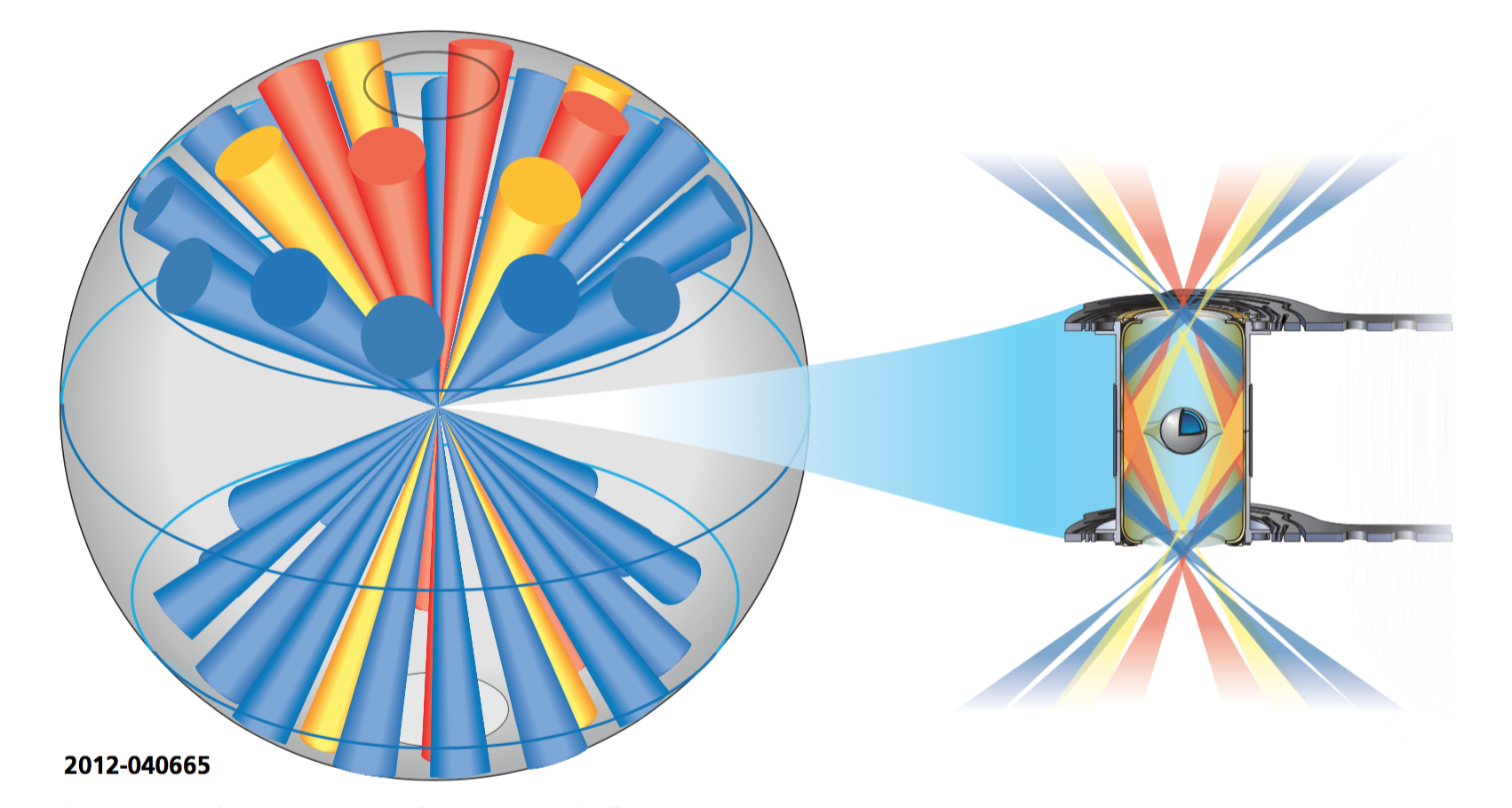
Figure 4-3. NIF beams are arranged to support vertically mounted, indirect drive hohlraums/targets. The four cones of beams at 23.5°, 30°, 44.5°, and 50° polar angles as shown as red, yellow, and blue (for 44.5 and 50°) respectively.
NOTE: Ports that are marked as “ID” are for indirect-drive configuration only. The ports that are marked as DD are for direct-drive configuration only. The others are common for both configurations.
Once the beams in a quad enter the target chamber, they pass through the final optics assembly (FOA) where the 1w light is frequency tripled to its third harmonic, 3w. Figure 4-4 shows a schematic of the FOA optical layout. The frequency converted 3w beam, nominally 37 cm square, is focused onto the target with a 7.7 m focus lens that is wedged slightly to separate the best focus 0.351 μm laser light from the residual 1.053 and 0.532 μm unconverted light. The effective aperture is 1250 cm . A quad of beams has a center–center spacing of 55.7 cm in the azimuthal direction and 63.2 cm in the polar direction. The f/# of an individual beam is 20.7, and the f/# of a quad is 7.9.
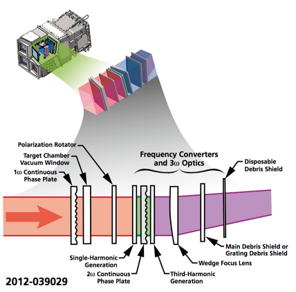
Figure 4-4. Schematic layout of NIF’s final optics assembly for a single beamline. The mechanical system mounts to the NIF target chamber and contains the final set of optics for four NIF beamlines (one quad).
Individual beams are pointed near chamber center by tilting the LM5 and LM8 turning mirrors. The currently permitted range of pointing for each beam is nominally ±30 mm up/down and ±5 mm left/right in beam coordinates and ±30 mm in Z (along the beam direction) about the target chamber center (TCC). There are beam-specific limits imposed to manage near-opposed light and final turning mirror aperture issues. These limits are managed with a pointing range check in the Shot Setup Tool (SST).