Overview 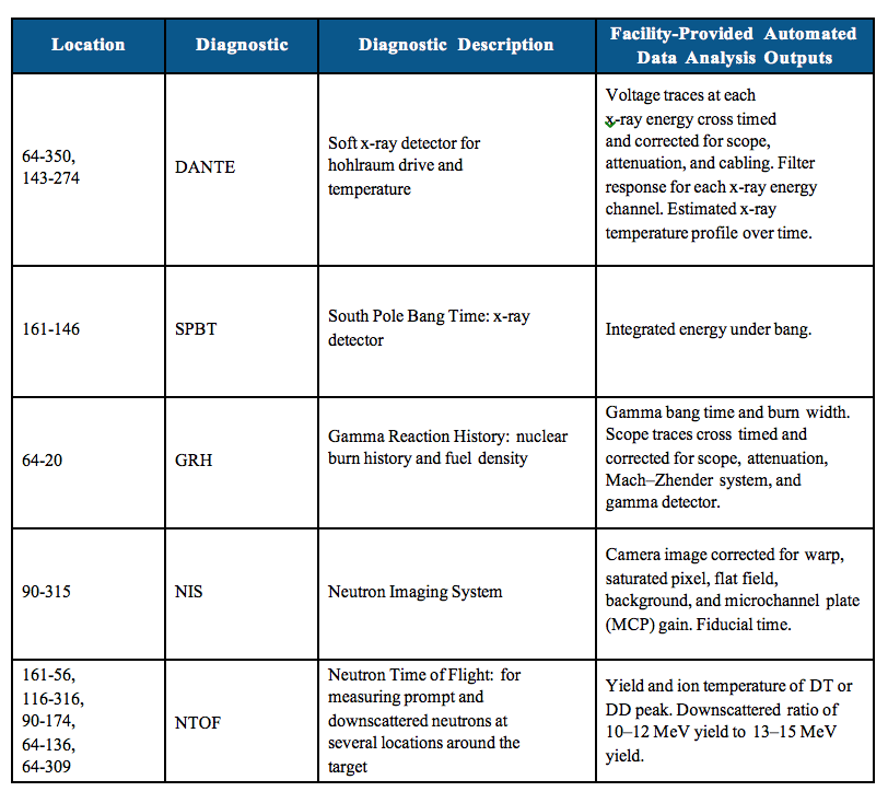
Large laser and pulsed power facilities at national labs such as LLNL have afforded the scientific community significant experience with measuring high-energy-density plasmas and with developing routine, reliable, and accurate diagnostic suites. NIF’s diagnostic development benefits from those decades of experience and from the involvement of organizations such as the University of Rochester’s Laboratory for Laser Energetics, Massachusetts Institute of Technology, General Atomics, National Security Technologies, and the UK and France’s atomic energy agencies.
NIF is equipped with an array of nuclear, optical, and x-ray diagnostics that together provide over 400 channels for experimental data. New instruments are added regularly (see https://lasers.llnl.gov/for-users/experimental- capabilities/diagnostics). Optical diagnostics measure the backscattered light’s power, spectrum, and angular distribution of visible light to determine the energy balance of an experiment as well as the implosion velocity of the fuel capsule, laser–plasma interactions, and instabilities that affect the target performance. Hard and soft x-ray emission detectors with micron-scale and picosecond-scale resolution characterize laser and target performance by measuring target self-emission or by using the x-rays to probe or radiograph dense matter. Nuclear diagnostics signal the presence of high-energy neutrons and gamma radiation and measure physical properties such as neutron yield, ion temperature, bang time, core temperature, and reaction history.
NIF diagnostics are either deployed to a fixed location in the target chamber/bay or fielded on a Diagnostic Instrument Manipulator (DIM). DIMs are two-stage telescoping devices capable of inserting, retracting, positioning, and aligning a diagnostic instrument in the target chamber, from the interior wall to Target Chamber Center (TCC). DIMs can t in a number of designated target chamber ports, but three are currently mounted in two locations: one in the target chamber north pole (0-0) and two on its equatorial plane (90-78 and 90-315); see Section 5.3. DIMs also provide a standard set of utilities, cables, and controls to support operation of all DIM-based diagnostic instruments.
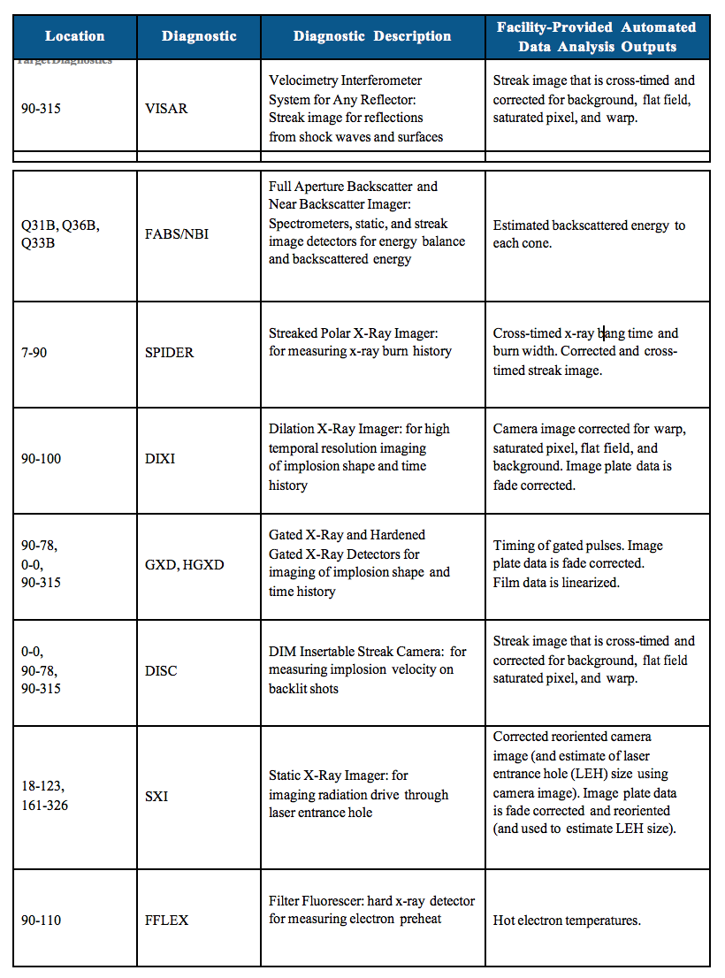
Facility-provided diagnostics data locations are listed in Table 6-1. Table 6-2 lists key DIM snouts and appendages that can be used in conjunction with a DIM-based detector. Figure 5-3 shows the location of the DIMs, target positioners, and major fixed diagnostics. Appendix E identifies the NIF diagnostics and detectors available. The diagnostic location is given in terms of chamber coordinates. Diagnostics labeled “DIM” may be placed in any of the DIMs. If an instrument at a fixed location requires a pinhole or filter on a DIM, this is noted.