Frequency Conversion and Unconverted Light Management 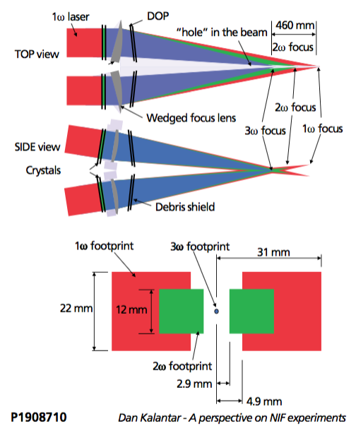
Primary operating wavelength for the target shots on NIF is the third harmonic of the 1053 nm fundamental wavelength at 351 nm. Efficient conversion of the amplified 1w light to its third harmonic is accomplished by a pair of non- linear potassium dihydrogen phosphate (KDP) and potassium di-deuterium phosphate (KDP) crystals installed in the beamline FOAs (Figure 4-4). First crystal combines two 1w photons into a second harmonic photon at 527 nm (second harmonic generator or SHG) and the second crystal combines a 1w photon and a 2w photon into a 3w photon at 351 nm (third harmonic generator or THG). The crystal thicknesses and cut angles are chosen to optimize the peak power conversion efficiency. However, since the conversion efficiency varies with intensity and experiments often require shaped pulses (such as those shown in Figure 4-6), there is a considerable amount of unconverted light remaining on NIF beamlines, particularly for shaped pulses. Most of the unconverted light is in 1w.
The frequency conversion at the NIF FOAs results in all three harmonics (1w, 2w, and 3w) entering the target chamber. The final focusing lens for each beam is wedged slightly to separate the three harmonics at TCC. Figure 4-7 shows the pattern of 1w, 2w, and 3w light from a single quad when looking in the 3w focal plane. The chromatic dispersion of the focus lens = combined with the wedge angle of the lens gives a separation of ~2.9 mm between the closest 2w beam edge from the 3w aim-point and ~4.8 mm between the closest 1w edge and the 3w aim-point. The overlap becomes more complicated when multiple beams are focused to a given point. Figure 4-8 shows an example of the distribution of 1w footprints from 96 NIF beams (upper hemisphere beams, for example) pointed and focused at TCC. If this unconverted light is propagated past focus, it hits beam dumps at the far wall. Mitigation strategies to deal with the effects of the unconverted light are discussed in Section 5.6.1 and 5.6.2.
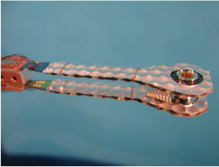
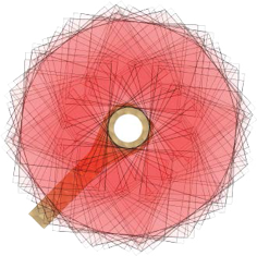
Figure 4-7. (Top) Distribution of the unconverted 1w and 2w light at the 3w focal plane from the NIF beams within a quad. The footprints from the two other beams in the quad overlap these.
Figure 4-8. (Left) Cryogenic target with dimpled 1w light shield. (Right) Schematic display of the 1w and 2w unconverted light footprints from the 96 beams from one NIF hemisphere (upper or lower) in the plane of the unconverted light shield.